You CAN also use, for input devices, the 5v from the NoviceGuard which is on the outside pin. And you don't NEED to use it with every output device. It was just a coincidence that I only used it on the examples of daughter boards for outputs.
Click this for NoviceGuard main page
This page is a sub-menu for pages about daughter boards for NoviceGuard. You do not need a NoviceGuard to use what is presented here. It will be of limited use if you do not have an Arduino.
NoviceGuard uses daughter boards let you plug things into an Arduino without all the fuss (and opportunity for mistakes) of using breadboards.
Don't be mislead by the term daughter board... many times, what you plug into a daughter "board" socket, will be simply a cable with a plug for the socket, and a small bit of electronics at the other end, perhaps nothing more than a little blob of plastic with two or three pins.
NoviceGuard is working, but there are frontiers as yet not fully explored. Some of the daughter boards mentioned here are fully developed, with support pages to go with them. Others are "works in progress"... but I hope they will inspire you to come up with your own daughter boards, and write in, tell me about them!
In this section, links to full pages about particular daughter boards.
Connecting A Potentiometer via NoviceGuard daughter board socket (Ng_PwrDemand_1): Okay, a pot is not the most exciting component on the planet... but even the lowly pot has uses. You could use one, for instance, to choose between, say, 20 modes of operations for something flashing pretty lights. That's a bit beyond the 4 that are available easily with the 4 buttons!
The page explains how to hook up a pot, but it also gives you quite a good lesson in some general points of the programming art.
Sensing light levels: When you are comfortable with the material about connecting a potentiometer, have a look at my page about sensing light levels. I hope you will see that hooking any of them up is a simple matter, probably requiring nothing more than Ng_PwrLevel_1.
Pretty stuff! Four DS2812 SmartLEDs on a NoviceGuard daughter board (Ng_PwrDemand_2): A page with software and a description of the necessary hardware. The DS2812 is a clever and pretty LED module. It has three very bright LEDs in it, one red, one blue, one green. You can "tell" it to make each one any brightness from "off" (0) to "full" (255). And you can connect a few easily, and dozens almost as easily... though not cheaply!... to a single pin of an Arduino, and it can "talk" to each SmartLED in the array over that single channel. (Each SmartLED has an "address" in the array... that's "the trick" of it.) The page also explains how to hook up strings of SmartLEDs from other sources. DS2812 smart LEDs are at the heart of the splendid things you can see at CubeTube.org... 3D cubes of colored LEDs doing cool things. And you can buy the cube in a "slot together, no soldering" form. (See CubeTube.org for links.)
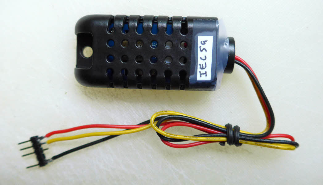
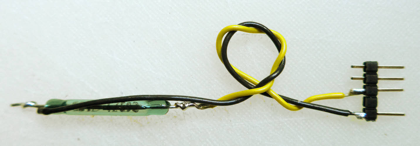
Humidity/ Temperature sensing. (DHT22. Other family members easy, too.) How to use a DHT22 humidity/ temperature sensor on a NoviceGuard has been written up for you. The DHT devices are a family of inexpensive and easy to use temperature / humidity sensors.
I had a little test program running in under 40 minutes, without hassle. That included going off onto the web to find things, and the "one off" chore (minimal) of installing a library. The first time I did this, I used the Adafruit DHT library, explained at AdaFruit's tutorial on the DHT series sensors. I didn't bother with the pull up resistor they suggest, but my tests were only brief. It might be a good idea. Not sure. (NoviceGuard "connects" the internal pull up on the input.) In the page this links to, the software used was that of Rob Tillaart, as listed at the official Arduino page, in the Playground.
Here's something you don't want to tell the novices too soon: The DHT sensors... and the excellent Dallas 1-Wire sensors, which I also believe will work fine on a NoviceGuard (but have not yet tested)) use their data line in BOTH directions. It is used both for input, and for output. What is in the NovGrdCore library does not interfere with this. However... should the sensor be plugged into an input daughter board socket, or and output daughter board socket?
The first part of the answer to that is: How has it been wired? The one on the illustration is wired to be plugged into an output daughter board socket. Odd, I know. I suspect that you could use the DHT sensors through an input daughter board socket, too. You would either connect the yellow wire to a different pin, or... and I can't see why it wouldn't work... connect the pin you see the yellow wire on to the center pin! For a variety of reasons, I am initially most happy with the sensor on an output daughter board socket... despite the confusion that will give novices, seeing as the sensor is most obviously an INPUT device. Sigh. I will give the matter further thought. Maybe delay introducing these sensors until your novices have a little experience built up!
RHT02: Humidity from 0-100% RH, accuracy +/- 2%... but avoid condensation... and insects/ spiders!
Temperature from -40 - 80° C, accuracy +/-0.5° C
I bought mine from a supplier who gives quick service, a wide selection, and good support for $20. Very similar devices, some of them with different ranges or accuracy, are also available. I've seen them sold for $3 (7/15)
Bottom line: The RHT02 works... easily... through a NoviceGuard. And it is likely that the DHT22, or DHT11 would do the same.
Really simple temperature sensing. (LM35DZ) How to use an LM35DZ temperature sensor on a NoviceGuard.
Control your Arduino with domestic remote control. Use, say, your TV's remote control as a "keyboard" for sending commands to an Arduino. Does require that you install a library. Uses one digital input line.
There is also information elsewhere about the whole idea of the daughter boards. That is mostly about what is on the NoviceGuard side of things. Here we will take a look at the daughter board side, in general terms...
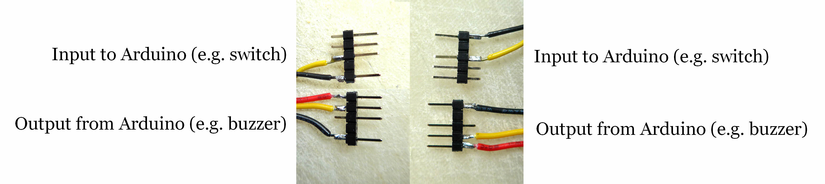
The following will, I hope, help you see how the wiring goes.
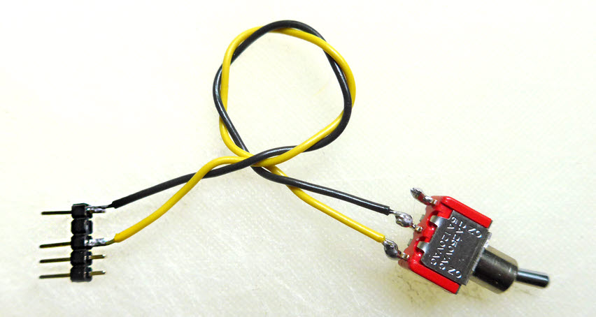
The black wires interconnect the ground of the daughter board with that of the NoviceGuard and Arduino.
The red wire is where your Vcc (5v or 3v3, or, in advanced usage, a voltage of your choice) comes into the daughter board from the NoviceGuard. Those volts may come from through the Arduino board, from whatever powers it, or from an independent supply, depending on what links you have made on the NoviceGuard. Be careful that the total current demand from all the connected daughter boards remains within the specs of the power supply.
The yellow wire is the data line. The upper examples are wired for inputs to the Arduino from the daughter board, for example id the daughter board were merely a switch.
The lower examples show the wiring for sending data out from the Arduino to the daughter board.
Note a feature of the design: If you were to take one of the daughter boards from the left, and try to plug it in on the right, it would be fine! (As long as you only plugged an input daughter board into an input daughter board socket. If you made a mistake, plugged an input board into an output socket (or vice versa), no harm would be done. It wouldn't work! But no harm would arise.)
However! Beware! In order to make every daughter board "pluggable" to either left or right, the order of what is on the pins is "reversed" (vertically). On the left side, the bottom pin is used to connect the grounds. On the right it is the TOP pin. Care!
You CAN also use, for input devices, the 5v from the NoviceGuard which is on the outside pin. And you don't NEED to use it with every output device. It was just a coincidence that I only used it on the examples of daughter boards for outputs.
It isn't rocket science, but a tedious detail that NoviceGuard and NovGrdCore are trying to shield novices from is that care must be taken to match the programming of the Arduino to the hardware connected to it. In particular, most peripheral hardware can be classed as either an input device, or an output device. And the Arduino would be programmed accordingly.
Of course, with a NoviceGuard, at least until you start using the Twelve Way Connector, you don't have to worry about these things. The peripheral hardware is connected via the daughter board sockets, and they are set up so that input sockets only accept input devices, and output sockets only accept output devices, and even if you DID plug something into the wrong socket, no harm would arise. (No result would arise, either... that includes no BAD result.)
However, some devices do both input and output.
Don't worry... all the clever stuff is taken care of by libraries you will use with those clever devices. But you will sometimes see what seems to be an input device set up as an "output" device. The DHT22 temperature/ humidity sensor is one such device. It is a SENSOR! It tells the Arduino about the temperature and humidity of its surroundings. But it is wired as an output device! It plugs into an "output" daughterboard socket.
This is because the sensor is a clever device, and the Arduino has to output some commands to the sensor before the sensor will respond.
There is more on this... things no novice needs to read, but perhaps useful to mentors, and other non-novice readers of these pages on the page "InpAndOutp.htm".
This section is for promises that work is being done. Not "written up" yet... but these things DO work on the Arduino, fear not!
--------------------
I have successfully "driven" the marvelous 1.8" Color TFT LCD display with MicroSD card from Hobbytronics (£24 incl VAT, excl p&p, July 2015) via a daughter board socket. (I didn't try to use the SD card socket, but believe it can easily be used as the source of static images to be used as part of the delay. It can even written to.. but perhaps not so easily as you can do the other things.)
The Adafruit 1.8" Color TFT LCD display with MicroSD Card Breakout ($20, plus p&p) is a similar product. Same display at the heart of it, but different pads for the user's connections to the device.
160x128 pixel TFT color display with 18-bit color
These images do not do justice to the CRISPNESS of the display, nor to the range of colors available....
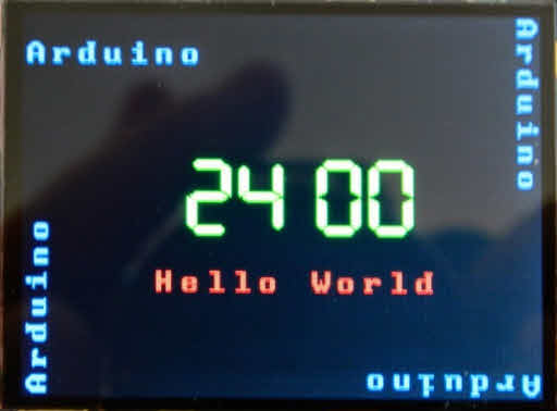
Go along to Google, search on "ST7735", switch to the page of images. The device is quite capable of a reasonable rendition of a photo.
And you "tell" the display what you want it to show with easy "almost English" commands. If you just want some text on the screen you just send the text. If you want to send it a "change font size" command first, you can... but that is optional.
Moving on again...
--------------------
Some "daughter boards" will be very simple, but useful, anyway... e.g. different types of switches from the ones already available on the NoviceGuard itself. (The on-board switches don't have to be isolated by cutting the traces provided for that, by the way, when you use an external switch. (As long as you are careful not to inadvertently press an on-board switch. Anyway- they make a good way to test if a failure is perhaps due to a faulty external switch.)
The following were both tested... Work! The wiring is EXACTLY right! (Toggle switch on left, reed switch on right. (Reed switch is closed by a magnet. There are lots of uses for them!)
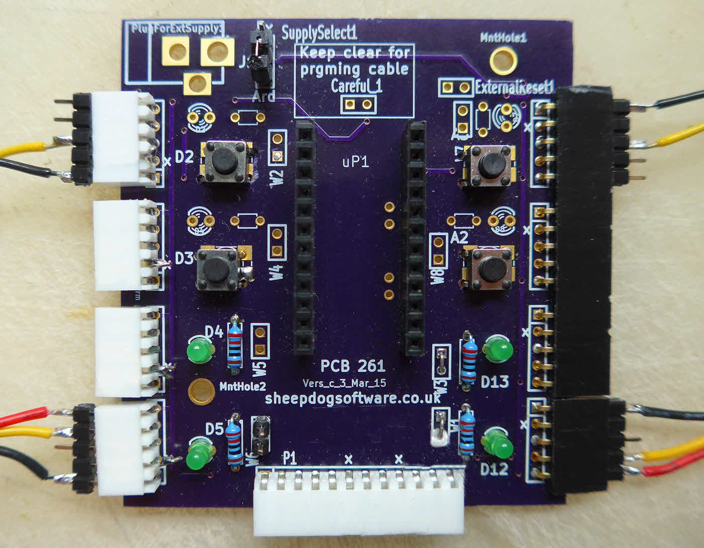
By definition, in the NoviceGuard context, a "daughter board" is something that plugs into one of the four 5-way sockets on the left or right hand edge of the NoviceGuard board.
The NoviceGuard board also has a twelve way connector on its bottom edge. The things that plug in there are not, in the NoviceGuard context, to be referred to as "daughter boards", please. The best term for them that I've been able to come up with is "twelve way connector module".
So, having tried to convince you to distinguish between "daughter boards" (plug into 5-way sockets) and "twelve way connector modules", I hope you will forgive me for foolishly mentioning one of the latter here.
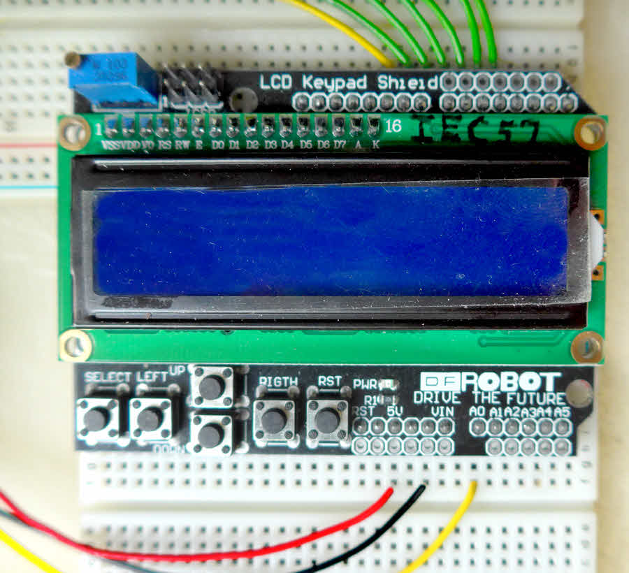
It is very much a work in progress, but I am confident that the following will connect nicely to an Arduino through a NoviceGuard in due course. I can already show you how to connect one of these inexpensive LCD displays with switches directly to an Arduino! (There's more information on these devices there. 16x2 character backlit LCD screen, up/ down/ left/ right/ select switch matrix... all about $8 and easy programming!)
![]() Page has been tested for compliance with INDUSTRY (not MS-only) standards, using the free, publicly accessible validator at validator.w3.org. Mostly passes, just a few "No attribute" issues, arising from Google code.
Page has been tested for compliance with INDUSTRY (not MS-only) standards, using the free, publicly accessible validator at validator.w3.org. Mostly passes, just a few "No attribute" issues, arising from Google code.
....... P a g e . . . E n d s .....