Click this for NoviceGuard main page
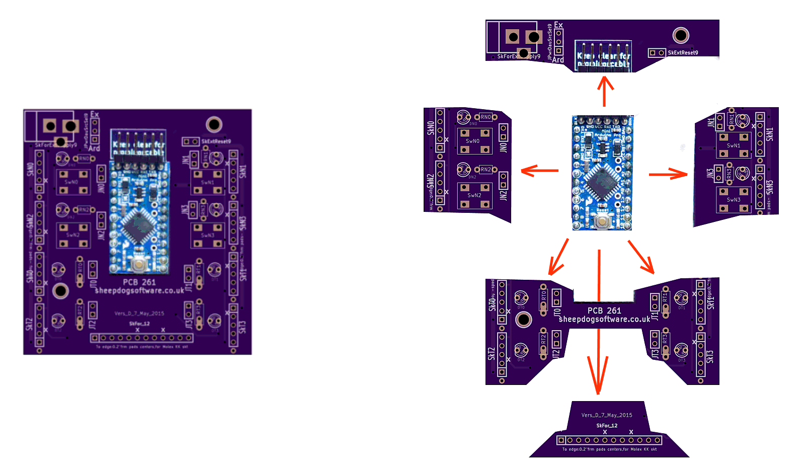
On the left below: an unpopulated NoviceGuard board (purple) with an Arduino Pro Mini (for scale, and to show where Arduino Pro Mini plugs into the NoviceGuard.)
On the right, the same image, but "exploded", to show you the "parts" of the NoviceBoard. Each part delivers related services from the board.
We will shortly take a first look the purpose of each sub-part. If you want more detail, it can be found at "More detail on the parts of the NoviceGuard board"
This page is a sub-page of the information for NoviceGuard (PCB 261). For more information please see the NoviceGuard main page.
PLEASE: Spread the word that NoviceGuard MIGHT be worth looking at, if you want the project to continue. I only ask that people look at the pages, not that they send any money.
I am now looking for teachers and electronics savvy parents actually working with kids with Arduinos in schools or homes for comments and further testing. I will loan you a NoviceGuard, if you will do something with it! (Email link at bottom.) (Further details on obtaining NoviceGuards.)
NoviceGuard is a small PCB with a few very dull components on it, and sockets users can use (optionally) to plug in more interesting components, carried on "daughter boards".
This is an open project. You can download a PDF of the overall NoviceGuard (PCB261) schematic, if you want to. Alternatively, these pages will take you gently through the parts of the board.
There are very few components which must be installed on the PCB. Only put on it the things you need.
The pull up resistors on inPUR, inPLR are an exception to that rule. They can be soldered directly to the board... probably a bad idea, unless you users simply won't be able to resist fiddling with them if installed as I would suggest: On pins to be plugged into sockets on SkN1, SkN3.
The PCBs, fresh from the factory, have thin traces shorting the pads for some of the option select jumpers. These thin traces save you the nuisance of soldering in pins, and providing a shorting "hat" to elect what I suspect will be the usual choice in some of the jumper-controlled matters.
The "choose between two" three pin jumper set JPwrDauSrcSel9 has a thin trace between the center and bottom pins. It is vital that you cut this trace if you install pins here.
The pads on the jumpers on the four output lines (JT0, JT1, JT2, JT3) also have thin links on the underside of the board. Cutting them "disconnects" the output LED (and its resistor). Solder in pins, put a shorting "hat" on them to re-connect the LEDs.
There are four output channels immediately and easily available. A very basic NoviceGuard will carry four LEDs. (NoviceGuard still "works", even if you decline to install some or all of them. That applies to almost any component.)
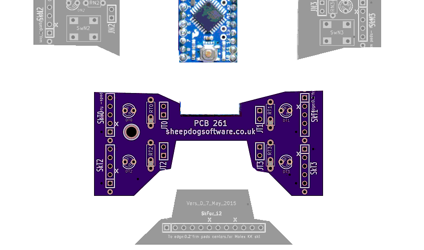
Look closely at the image above, and you will see, somewhat more spread out....

What we see at the left are the positions where the four LEDs go on the NoviceGuard. (The LED names are, from upper left, as you would read a square of four words: DT0, DT1, DT2 and DT3. The names are inspired by, for the first one: "Diode, on ouTput, position zero (0)". This "0,1,2,3" numbering of elements of NoviceGuard is echoed elsewhere, too. for instance, the NovGrdCore library has output routines. (These naming conventions are discussed in greater detail on the "technical detail" version of this page about the NoviceGuard hardware.)
Users are not restricted to turning an LED on and off. By means of daughter boards, "fancier" hardware can be plugged into the NoviceGuard, to extend what your users driving with the Arduino's outputs.
There are four input channels immediately and easily available. A very basic NoviceGuard will carry four push button switches. (Momentary SPST switches.)
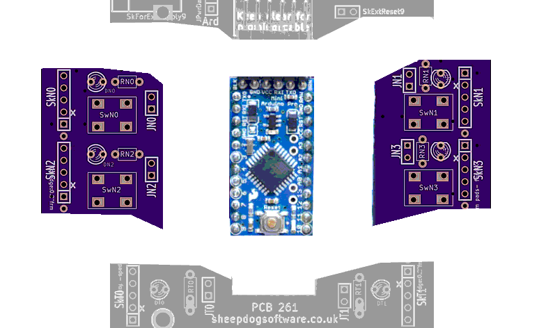
The four switches go at the rectangles marked SwN0, SwN1, SwN2 and SwN3, which I hope you see clearly on the image? (SwN3: SWitch, to provide iNput, in position 3.)
Novice NoviceGuard users can be allowed to think there are four digital inputs. The boardseems to have four similar inputs, if used via the NovGrdCore library. Or if the board is used with the avoid-the-library "tricks" explained elsewhere. Use of the library is optional. Use of the NoviceGuard is optional! Your learners can still use the challenges and help on these NoviceGuard/ NovGrdCore pages!
The two inputs on the left (Input "0" and Input "2") are indeed simple digital inputs. The two on the right (Input "1" and Input "3"), however, are analog inputs. Intermediate NoviceGuard users can use them as such. But beginners don't need to be confused by the differences. (The logic and implications of all this is explained more fully in the page with the technical details of the NoviceGuard hardware.)
As before, users are not restricted to only the push button switch. By means of daughter boards, "fancier" hardware can be plugged into the NoviceGuard, to extend the inputs your users read.
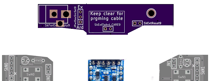
Novice NoviceGuard users would not be making changes to the power options; that would be a job for whomever was introducing the novices to the Arduino. There's much on these matters at my pages about the Power Demand Scenarios, e.g. NG_PwrDemand_0. (It isn't as fearsome as it sounds. Can be "just used" by struggling mentors, but helpful, too, I hope, to "mentor mentors".)
Details are in the page with the page with the technical details of the NoviceGuard hardware. They include an explanation of the SkExtReset9 socket, which isn't to do with power, even though it is near the power select elements of NoviceGuard.
I promised earlier that NoviceGuard users are not limited to just four lines of input, four of output.
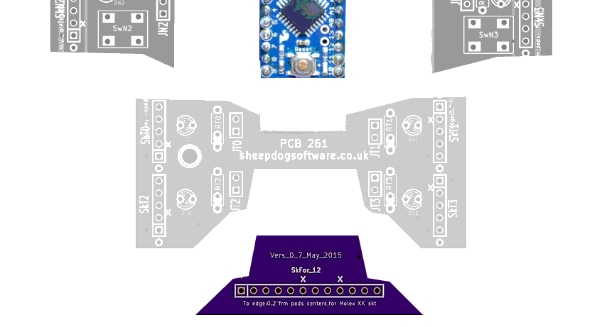
The additional lines are available by plugging daughter boards in to the twelve way socket on the bottom edge of the board. There's more on this in the technical page about the NoviceGuard board.
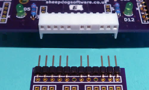
I used PhotoPlus to "improve" the "no pin here" positions on the socket. Don't hunt for 12 way strips with positions 6 and 9 so nicely blanked! (There are plugs you can insert, or just carefully seal the socket with a "scar" created with the tip of a soldering iron.
Understand the basic hardware, and you more or less understand NoviceGuard. But other pages give you more detail, give you the above again but from a different point of view.
This page is intended as only an overview of the NoviceGuard hardware... and you've had that. (I go into greater detail in a similar page, if you are ready for that.)
You can... and should... just use NoviceGuard the "simple" way. At first.
And when you are ready for more, NoviceGuard has that for you.
There are eight 5-way sockets around the edge of NoviceGuard.
Note A: We tell the novice novices that the board has "4 inputs", anyway. When they become more proficient, then we broaden their knowledge, explain that actually, the inputs on the left are digital, and the inputs on the right are analog, even though the free NovGrdCore Arduino library gives them a boolean function... one... which reads any of the four inputs the same way as it reads any of the others. And when our novices are a little further along, or if NoviceGuard is being used by an experienced person, then those analog inputs can in fact be used more flexibly. See the page about the NovideGuard's inPUR and inPLR inputs for the details.
Back to the broader issues...
The eight 5 way sockets are for small, simple (inexpensive!) daughter boards which can be created, in any number, and in many forms.
However, do not assume that "just anything" can be plugged into the sockets for the daughter boards. Users would have to restrict themselves to daughter boards approved by their helper-of-beginners. If the circuit on the daughter board allows too much current to flow out of the Arduino, or into it, things will not go well. Fortunately, a way to power more demanding devices exists, which we will come to later... though I may not have that written up yet!
Hopefully, as NoviceGuard gains momentum, people who know enough to design safe-for-the-Arduino daughter boards will share their ideas with the NoviceGuard community.
On the sockets for daughter boards, the second pin's hole is blocked. The daughter boards should have no pin in position 2. Thus, the daughter boards are polarized, can only be plugged in the right "way around".
Users might accidentally plug an "output" module into an "input" socket!
Features in the design ensure that no problem will result. (The module won't "work" in the "wrong" socket(!)... but nothing will come to any harm.)
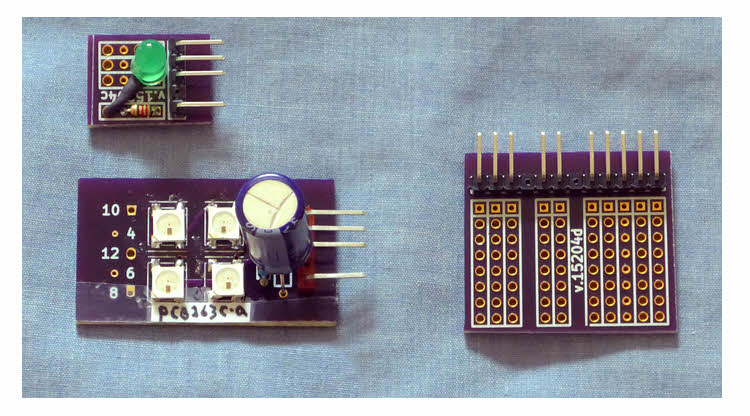
The illustration shows a few daughter boards, and something even fancier.
From top left, counter-clockwise, we have: a simple LED, but larger than the ones on NoviceGuard itself, and you could of course use LEDs of various colors.
Then a daughter board carrying four WS2812 "Smart" LEDs... these are really cool... very bright, any color from each, all four controlled by one digital output. More at my page about WS2812s via a NoviceGuard.) (These daughter boards would require the NoviceGuard's "advanced" daughter board powering arrangements... but they aren't terribly complex... just something to postpone until you are comfortable with using it in the first mode.)
And lastly, the large thing on the right: This is an unpopulated unit for the 12 way connector which is on the bottom edge of the NoviceGuard... Not a "daughter board", within the meaning of the act, but similar in some respects. Written up at the bottom of the page that covers the ground this page has covered, but in greater depth.
This page is a sub-page of my Rugguino site, and a sub-page of the information for NoviceGuard (PCB 261). For more information please see the NoviceGuard main page.
![]() Page has been tested for compliance with INDUSTRY (not MS-only) standards, using the free, publicly accessible validator at validator.w3.org. Mostly passes, just a few "No attribute" issues, arising from Google code.
Page has been tested for compliance with INDUSTRY (not MS-only) standards, using the free, publicly accessible validator at validator.w3.org. Mostly passes, just a few "No attribute" issues, arising from Google code.
....... P a g e . . . E n d s .....