Click this for NoviceGuard main page
Preliminary checks on two batches of PCBs for NoviceGuard have gone well, and a third is being made up! No flaws found in original design, but we now have two "tweakings" improving trivial things.
This page is a sub-page of my Rugguino site, and a sub-page of the information for NoviceGuard (PCB 261). For the overview of NoviceGuard please see the NoviceGuard main page.
Well... I've spent time. (many, many hours). I've spent money. (Making boards, getting in components.)
I've spent time trying to make a market aware of this project.
Yes, the page is rough around the edges... but does it really not give enough of an idea of what NoviceGuard does to excite interest? No one seems to be "Liking", forwarding, mentioning in blogs, etc.
So I conclude that either it doesn't do what I think it does, or that no one is interested in bringing Arduinos to kids, and will move on to other projects if interest doesn't pick up.
YOUR CHOICE Spread the word that this MIGHT be worth looking at, if you want the project to continue. I only ask that people look at the pages, not that they send any money.
I am now looking for teachers or electronics savvy parents) actually working with kids with Arduinos in schools (or homes) for comments and further testing. I will loan you a NoviceGuard, if you will do something with it! (Email link at bottom.)
There is a page dedicated to how to obtain NoviceGuards.
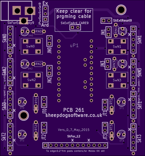
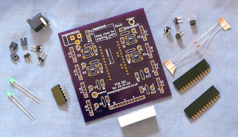
NoviceGuard is a small PCB with a few very dull components on it. It also has sockets to allow users to plug in more interesting components, carried on "daughter boards". So: It is flexible. (Beginner users would have to be persuaded to refrain from plugging "just anything" into those sockets... but many things are possible for a knowledgeable daughter board designer, without compromising the "protect the Arduino" function of the NoviceGuard. If NoviceGuard gathers momentum, I hope people will share the daughter board designs they have come up with.)
You can download a (readable! Good resolution!) PDF of the overall PCB261 schematic. The screen shots below could be from an earlier version of the schematic. Look in the lower right of the schematic, just above the box which has meaningless "Rev" (i.e. version) information in it. If I've remembered to update the text here, as well as the file you can download, the current schematic is from 8 May 15. It has the "improved" component references which I hope will remain constant from now on.
The prime objective of NoviceGuard is to protect the Arduino (and the system can be adapted for other microprocessors) from non-malicious novice users. Secondary objectives include making it affordable, and making the novice's life easier.
Nothing is entirely "safe", and to get the benefits, some things have to be given up.
NoviceGuard relies on the assumption that users can be persuaded... and the details of how are a matter for another day... NOT to use any pinMode statements other than the ones they are give, and TO use all of the ones they are given. As given to them. (27 Apr 15... I am moving towards a system based on an optional Arduino library which will, among other things, take care of the required pinMode statements. Users will just have to remember not to add any pinMode statements. See the page about NovGrdCore, the free Arduino library provided to you, to simplify using Arduinos.)
At the start of a basic "NoviceGuard-friendly" program, we will have something like the following. (The hardcoded pin numbers have been replaced by the more sensible device of a global constant to stand for the numbers given in the SIMPLE version below... (Also explained in the page about NovGrdCore.)
void setup()
//Do not alter this subroutine.
//Do call it at the start of setup()
//Do not add or remove any lines with "pinMode" in them.
{
pinMode(5,OUTPUT);//Do not delete or change this line
pinMode(6,OUTPUT);//Do not delete or change this line
pinMode(12,OUTPUT);//Do not delete or change this line
pinMode(13,OUTPUT);//Do not delete or change this line
8
pinMode(2,INPUT_PULLUP);//Do not delete or change this line
pinMode(3,INPUT_PULLUP);//Do not delete or change this line
pinMode(A2,INPUT_PULLUP);//Do not delete or change this line
pinMode(A3,INPUT_PULLUP);//Do not delete or change this line
}//end of setup()
Yes... one of the things we are giving up is the option to, say, use D2 as input or output. For NoviceGuard, it will be dedicated. (In the case of D2, as an input.)
So.. that (the restricted use of pinMode) is the sine qua none of my cunning plan. Too much to ask? Hope not! Onward....
As designed, if you want to keep things really simple, you just put the following on the NoviceGuard PCB. (Electing to start simple does not preclude getting fancier later. Nor does "getting fancier" preclude using the PCB in "simplest" mode later.)
That's it. That's all you need... for an extended course in Arduino programming. (There may be a need for one more pair of resistors... there's a little gap in the design only just noticed! But they are not likely to be any great "big deal".)
Of course, going on to, say, add a temperature sensor, a buzzer, etc, etc... which you can do... makes it all more "fun". But I think you will be amazed how much can be done with just the hardware cited. And, note, no messing with breadboards, etc, for the novice.
So! (Thank you for your patience, while I was "setting the scene") What do I want from you?
(For the moment, I don't need things like "User could put the PCB down on a metal ruler, and short out things which ought not be shorted", please? For now, at any rate?)
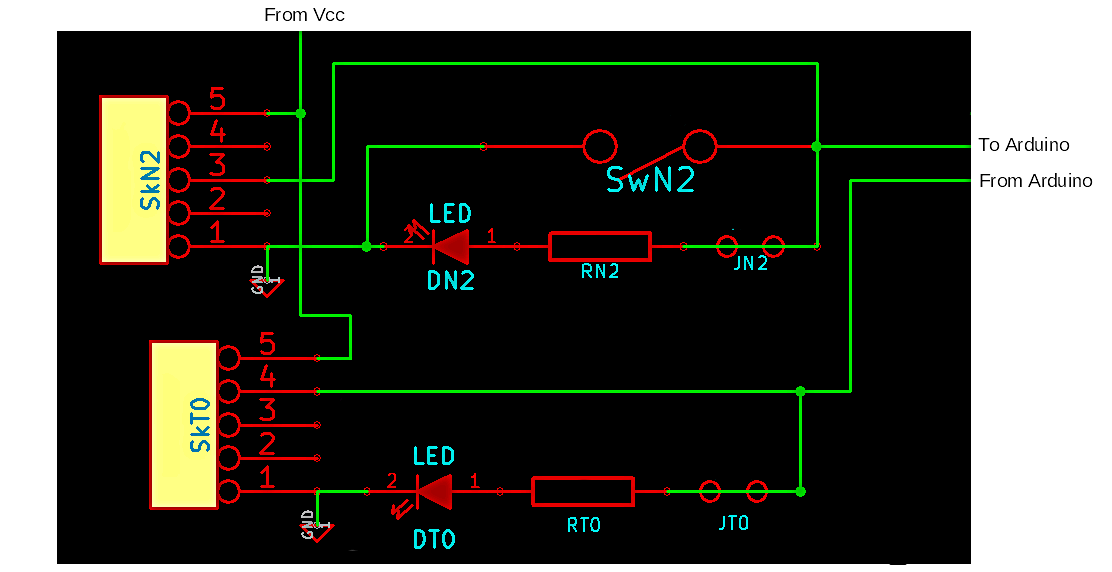
For now, we are just talking about the Arduino plus "basic" NoviceGuard. Nothing plugged into the sockets where daughter boards can be attached. So you can, for now, forget SkN2, SkT0 and the line marked outside the diagram as "From Vcc"
In the diagram above, we have one typical digital input (to Arduino) channel, one typical output channel. (NoviceGuard also allows the use of some of the Arduino's analog inputs.)
SwN2 is at the heart of an instance of the minimal electronics to send an input to the Arduino.
In the "basic" NoviceGuard configuration, neither the LED "DN2" (that's "Diode on iNput cell 2", not digital I/O line 2!), nor the resistor RN2 is present. Nothing is plugged into SkN2, but the connection between the left hand side of SwN22 and the Arduino's ground (indicated by the small triangle depending from pin 1 of SkN2) is present.
So far, so simple? What could a novice do to harm an Arduino with that hardware? (The line at the right of the diagram goes to an Arduino digital I/O pin, D3, as it happens, configured for input, with the internal pull up resistor "connected". (pinMode(x,INPUT-PULLUP);)
We'll come back to the circuit for input to the Arduino in due course. (When we do put DN2 and RN2 on the board, and/or plug things into SkN2)
From the Arduino's pin D4, we have a circuit through link JT0. (Jumper, ouTput channel, number zero (0)). (JT0 is for a link, but that link is made on the NoviceGuard as delivered. If you wish to put an elective link there, you sever the trace, and solder in two pins.)
Thence, current can flow through RT0 and LED DT0, to ground. Simple? Novice proof? What could possibly go wrong?
(I'll write up "what can be plugged into SkT0?" later.)
Moving on to a different part of NoviceGuard...
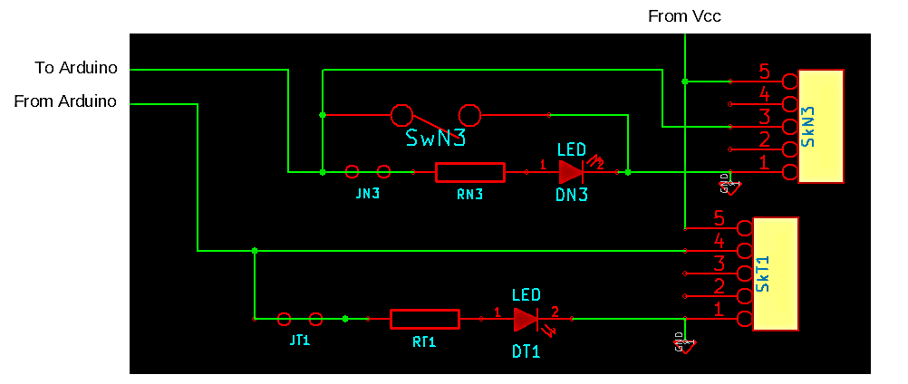
In the diagram above, we have one typical analog input channel, and another of the output channels. (There is nothing to discuss about the output channel. It is exactly like the one we already discussed.)
In the simplest configuration of NoviceGuard, RN3 and LED DN3 would be absent.
It will seem strange that I have put a simple switch on an analog input. There is a method in that madness.
The Arduino's pin 24, to which the left side of SwN3 connects, is one of its analog inputs, A3.
To use the NoviceGuard in the simplest way, add a 10k resistor between pins 3 and 5 of SkN3. Additionally, you will have to arrange for pin 5 of SkN3 to be carrying the Arduino's Vcc. There are and will continue to be ways to arrange this, but this side of things is yet to be properly written up. (Yes, the issue of not exceeding the Arduino's power limits is being included in the considerations. It is, indeed, the main issue giving rise to things that are easy to use, but hard to describe.)
This insertion of a resistor can be via one carried on a small strip of 0.1"-separated-pins to plug into a socket provided at SkN3, if you anticipate using the daughter board option, or it can simply be soldered to the pads provided for that socket, if you want fewer things for inquisitive novices to fiddle with. (The resistor could always be removed later and provided on pins if you changed your mind about using the daughter boards.)
It will seem odd, but novice users' early experiments with the analog input will be along the following lines...
void loop()
{
int iAnVal;

iAnVal=analogRead(2);

if (iAnVal>800)
  {//indicate button on A2 NOT pressed
  }
 else
  {;//indicate button on A2 IS pressed
  }// end "else" block
}// end "loop()"
That's "it", for the NoviceGuard in simple mode! Pretty safe, I hope you agree?
Moving on...
Now I will consider those three elements of NoviceGuard again: The digital inputs, the digital outputs, the analog inputs.
But first, a little digression... the LEDs on the input lines.
In the first diagram, upper part, there's a resistor, RN2, and an LED, DN2. And "JN2", where two holes exist, shorted together by a narrow trace, in the PCB, as supplied.
The LED is there simply to give the user a visual indication of the input being sent to the Arduino at any given time. That wouldn't interfere with the operation of SwN2 as an input, would it? And when you start being "fancy", the LED can be disconnected by cutting the trace between the pads of JN2, if it does matter. If you want to re-enable it, just solder two pins into the pads, and put a "hat" (shorting device) on them. Make sense? Work? Without risk to anything?
.... end of "little digression!
Let's say that you want to connect a push button to the Arduino, but it needs to be several feet from it.
Simple! Just put it on a length of wire, and on the other end a 5 pin strip of 0.1" separated Molex KK pins, with the switch wired to pins 1 and 3. Pin 2 should be taken out of the strip, as the entry to the hole for pin 2 on the socket is blocked, to polarize the connector.
We'll be coming back to this in a moment. But first, external output devices....
Still referring to the upper diagram above, look now at SkT0.
If you wanted, say, to put a big LED on the output, again: Simples! Just put it, and a resistor, at the end of a wire. On the proximal end of the wire put a 5 pin Molex KK strip, pin 2 missing, LED and resistor connecting to pins 1 and **4**.
Notice!: The input daughter board communicates with NoviceGuard through pin 3 of the daughter board connector. The output daughter board communicates with NoviceGuard through pin 4.
Thus, even if a user makes a mistake, and, say, plugs a switch (which can pull pin 3 to ground) into a socket, damage to Arduino "shouldn't" arise.
Coming back, as promised, to inputs... they can, of course be things other than switches. And outputs can be things other than LEDs. And daughter boards may need a source of voltage for their circuits. this is provided for on the daughter board socket. All that I've been saying recently about "inputs" applied equally to digital and analog inputs.
Pin five of all the daughter board sockets is "fed" with either 5v or 3v3, depending on the Arduino you have set the NoviceGuard up for.
There is a way to tap into the Arduino's 5v (3v3)... and that may be appropriate, in some cases. But there is also a way to supply those pins with voltage from a separate source, if the power required by the daughter boards available to your novices would exceed the Arduino's specs. (SkForExtSupply9 and JPwrDauSrcSel9 are at the heart of this feature.)
The details of that will be discussed at a later date, if all of the effort to get this far gets a suitably encouraging response from the Arduino/ educator/ parent community. If no one is interested, I will cut my losses. Losses which include $120 worth of PCBs. So, please?...?
Even if you can say "I looked at what you have... carefully... and, as someone who knows a bit about these things... I can spot no problems so far."
So... that's an idea of what NoviceGuard is about. It grieves me that kids are not being "got started" at school in the fabulous world of micro-electronics. Be part of the solution!
NoviceGuard needs to gather momentum. In search of that, I will loan a NoviceGuard to suitable individuals. Write, tell me why I should loan you one. If I cannot send it to you c/o a school I can research on the web, it will help if you are an established contributor at the Arduino Forum.
There is a page dedicated to how to obtain NoviceGuards.
This page is a sub-page of my Rugguino site, and a sub-page of the information for NoviceGuard (PCB 261). For more information please see the NoviceGuard main page.
![]() Page has been tested for compliance with INDUSTRY (not MS-only) standards, using the free, publicly accessible validator at validator.w3.org. Mostly passes, just a few "No attribute" issues, arising from Google code.
Page has been tested for compliance with INDUSTRY (not MS-only) standards, using the free, publicly accessible validator at validator.w3.org. Mostly passes, just a few "No attribute" issues, arising from Google code.
....... P a g e . . . E n d s .....