Click this for NoviceGuard main page, http://tinyurl.com/NoviceGuard.
This page is a sub-page of my Rugguino site, and a sub-page of the information for NoviceGuard (PCB 261). For more information please see the NoviceGuard main page, http://tinyURL.com/NoviceGuard.
Well... I've spent time. (Many, many hours). I've spent money. (Making boards, accumulating components.) I've not asked anyone else to put their money into it.
I've spent time trying to make a market aware of this project.
Do the NoviceGuard pages really not give enough of an idea of what NoviceGuard does to excite interest? No one seems to be "Liking", forwarding, mentioning in blogs, etc.
I am beginning to think that either it doesn't do what I think it does, or that no one is interested in bringing Arduinos to kids, and will move on to other projects if interest doesn't pick up.
YOUR CHOICE Spread the word that this MIGHT be worth looking at, if you want the project to continue. I only ask that people look at the pages, not that they send any money.
I am looking for teachers or electronics savvy parents actually working with kids with Arduinos in schools (or homes) for comments and further testing. I will loan you a NoviceGuard, if you will do something with it! (Email link at bottom.)
Keep these in mind, and they may help you find your answers if anything puzzles you.
NoviceGuard had two primary goals design objectives:
i) If users co-operate in just a few things, they will not accidentally damage the Arduino they are using.
ii) NoviceGuard makes things easier for novices. It saves them the hassle and responsibility of hooking things up (properly!)
Suggestion: This page is "browser friendly". Make your browser window as wide as you want it. The text will flow nicely for you. It is easier to read in a narrow window. With most browsers, pressing plus, minus or zero while the control key (ctrl) is held down will change the text's size. (Enlarge, reduce, restore to default, respectively.) (This is more fully explained and there's another tip at my Power Browsing page.)
This page is probably the least developed of all the pages relating to NoviceGuard.
My intention for this page is to create something mentors can print out, something with "everything they need" for those times when accessing the webpages online is not convenient.
Ha! More easily imagined than created... especially if you want to guard against elements of one page drifting away from what other pages say about the same thing. But here is an attempt, for you, anyway. Please remember that this is not all that is available to you!
A few links, like the one at the end of the last paragraph, in this will be useful only when you are online. (Or using a local copy of the .htm) In this page (only) I have tried to give you, as text, the URL of pages you might want to access when you have an ink-on-paper copy of this in your hand, and a computer on your desk. They must all be prefixed http://rugguino.com/
First: the rule in terms intended for mentors. Then suggestions will be provided for how it might be explained to novices.
I hope you will avail yourself of the free Arduino library NovGrdCore. (See http://rugguino.com/NovGrdCoreMain.htmNovGrdCoreMain.htm.
There are no "secrets" in it to worry about... you can examine all of its internal elements with a simple text editor. (For Windows, I like Textpad, see http://Textpad.com... or just use Notepad.)
But I know that not everyone is willing to use a library, so there are alternatives for those folks: They need to see NGCoreDoINeed.htm.
(There is more to NovGrdCore than we are going to discuss here. The rest will be discussed elsewhere in this manual.)
Fine print: No more, no less... until you start using modules plugged into the 12 Way Connector. Which won't be in your early NoviceGuard days, I hope! Even then, if using NovGrdCore, you won't need to do pinMode commands, as such.
There are two subsections here... one for if your novices are not using NovGrdCore, one for if they are.
If USING the free Arduino library NovGrdCore:
Using NovGrdCore is really just such a Good Idea. Please try to like the idea of at least trying it.
If you have installed the library, you and your novices only need the following in your code to take care of the #defines and pinModes described below in the "If NOT using NovGrdCore" section. A full "skeleton" program is presented shortly, to show you where these bits go.
...and...
All the pinMode command NoviceGuard needs are done by the code in the second line. This solution neatly "hides" the pinMode commands, helping to keep novices from using any others... which would be a Bad Thing.
Compliance with The Great Rule... "pinMode: Don't"... means that NoviceGuard can protect the Arduino from some of the mistakes novices make.
Here's the whole program for "Blinky", as modified for an Arduino on a NoviceGuard, compiled on a system with the free NovGrdCore Arduino library.
This could be a starting point for many other programs. Your users, while in their "crawling" stage, would only change things inside the curly brackets... {} s... after the loop().
//"Blinky" for NoviceGuard + NovGrdCore...
//Vers 26 Jul 15

#include <NovGrdCore.h>

NovGrdCore NGC;

void setup()
{
  //You need a setup()... even if it is only an empty one!
  //If you see a listing with NovGrdInit(), just delete...
  //   and please tell me where you saw it?
  //
  //You MAY need to put things here later... but not for Blinky
}//end of setup()

void loop()
{
//The four lines that follow are just
//  a little something to get you started.
//You can change or even delete them.
digitalWrite(ouPLR,HIGH);
delay(100);
digitalWrite(ouPLR,LOW);
delay(300);

//Your stuff goes here....
}//End of loop()
A lot neater than the NovGrdCore-less version, which I explain next, don't you think? A lot less "stuff" for novices to get lost in.
If NOT using NovGrdCore:
If not using NovGrdCore library, your users will need to put the following near the top of every program....
     #define ouPUL 4 //no ; here
     #define ouPUR 13 //no ; here
     #define ouPLL 5 //no ; here
     #define ouPLR 12 //no ; here

     #define inPUL 2 //no ; here
     #define inPUR 3 //no ; here ANALOG channel number
     #define inPLL 3 //no ; here
     #define inPLR 2 //no ; here ANALOG channel number
And, somewhere out of the way...
//======================================
void NovGrdInit()
//Do not alter this subroutine.
//Do call it at the start of setup()
//Do not add any other lines "pinMode" lines to your program.
{
pinMode(ouPUL,OUTPUT);//Do not delete or change this line
pinMode(ouPUR,OUTPUT);//Do not delete or change this line
pinMode(ouPLL,OUTPUT);//Do not delete or change this line
pinMode(ouPLR,OUTPUT);//Do not delete or change this line

pinMode(inPUL,INPUT_PULLUP);//Do not delete or change this line
pinMode(inPLL,INPUT_PULLUP);//Do not delete or change this line
... and they will need to be sure to do what the comment says: Call NovGrdInit() early in the setup() subroutine's code.
(Pins inPUR and inPLR do not need pinMode commands... their default modes are what we want.)
For those who choose to eschew the NovGrdCore library, the code above is necessary. Plus, for more complex exercises, some subroutines, as explained in the page about doing without NovGrdCore.
After those things are provided for... probably by giving your novices a boilerplate "starting point for every exercise"... your novices could be told (and helped to understand!)...
"Your code must start like this. You must not change the marked lines. You must not add any other pinMode commands. Initially, you will only put new stuff inside the curly brackets... {} s... after the loop().
void setup()
{
NovGrdInit();//Leave this as the first line of setup.
//Your stuff for setup() goes here....

}//end of setup()

void loop()
{
//The four lines that follow are just
//  a little something to get you started.
//You can change or even delete them.
digitalWrite(ouPLR,HIGH);
delay(100);
digitalWrite(ouPLR,LOW);
delay(300);

//Your stuff goes here....


}//End of loop()
The "using NovGrdCore" version (previous section) is a lot less messy, don't you think? There's a lot less "stuff" for novices to get lost in. Please at least TRY using NovGrdCore, (see NovGrdCoreMain.htm), even if, for some reason, you don't use it with Novices. (I would be interested in knowing your reasoning... after you have negotiated the "How Do I Use Libraries" speed bump, if you haven't used them before. It really isn't hard... and beats the alternative. There are notes on installing NovGrdCore in the page cited.)
Remember that to go NovGrdCore-less, you need all that "overhead" stuff as part of every program. Yes... you can pare some of the subroutines, if you are not using them in a particular program, but keeping track of which you need, which you don't is more trouble (and opportunity for frustration) than it is worth, don't you think?
Yes! I know that you couldn't just throw the "no pinMode commands" rule, or either boilerplate at novices. They would be part of what you would give them, to get them going with their Arduino adventures.
That concludes a major element of this User's Guide, the "What Is The Great Rule? How To Comply?" part. I hope you are left with a sense that the rule is easy enough to keep, despite the text about the whys and wherefores "going on a bit". Sorry. But some readers will, I hope, want to understand, not merely "do as told". And catering for the "won't use a library" crowd added a bunch of stuff.
The first design objective...
...is taken care of by aspects of the circuits, and The Great Rule. We've finished with that, okay?
---------------
We turn now to preventing another of the things that novices do to hurt Arduinos: asking them to handle excessive currents at the Arduino voltages.
Preventing power excesses is not as easy as the issues that The Great Rule resolves. No simple rule will do the job.
NoviceGuard is conceived as an aid to novices. With it, I hope, they can learn how to use microprocessors.
Learning is easiest when it starts with just few simple things and proceeds, one "problem" at a time. The tricky bit, for course designers, is to choose the "few simple things" that let the user have some fun in the early stages. Of course, in addition to the NoviceGuard specifics in this manual, novices may need to have help setting up their "big" PC with the free Arduino development environment, and they need to get to grips with the ordinary cycle of "Write source code. Save it. Compile. Upload object code. Test. Repeat." At least that is so much easier on an Arduino that it was on other computers in the not too distant past!
The microprocessor "Hello World", i.e. "wink an LED", aka in the Arduino world "Blinky", is where most people start for a good reason. There isn't much to "deal with"...
Pseudo code for what we want....

Repeat forever....
   Turn LED on
   Wait a bit
   Turn LED off
   Wait a bit
With a NoviceGuard, the LED (and its resistor) are already connected. The pinMode command is taken care of. If NovGrdCore is installed, Blinky is really easy. (Even without NovGrdCore, (NGCoreDoINeed.htm), it isn't hard.)
    //Arduino- with- NovGrdCore code....

    //(This not yet tested.. but should be nearly right...

    #include <NovGrdCore.h>;
    NovGrdCore NGC;

    void setup()
    {
        //a shell is necessary, even if empty
    }

    void loop()
    {
        makeOuUR(1);
        delay(400);
        makeOuUR(0);
        delay(400);
    }
That's it! Even Susan Parks should be able to manage it, don't you think?
(If you can tell me who Susan Parks is, you are a hero. More seriously: If you get to testing that before I do and can let me know it is okay (or of any errors... semi-colon, maybe?!(^_^).... thank you! (You don't need a NoviceGuard to use these examples, remember. You need the library, yes, but that is free. For the above, you either need an LED (and resistor) on pin 13, or, if your Arduino has the usual on-board LED on pin 13, you can just watch that go on and off, if the program is okay.)
... and I am! (Talking about the power demand scenarios. I was setting the scene for the start of "act one". We talked about the programming for "Blinky" earlier. But you also need to worry about power demands. "Blinky" requires the Arduino to drive one LED. This is okay under the "NG_PwrDemand_0" "power demand scenario"... which is what I am just starting to explain...
When novices first meets a NoviceGuard, I want them to have as little to worry about as possible.
To reduce the knowledge-needs, I would expect the mentor to give the novices their NoviceGuard protected Arduinos set up for what I call the "NG_PwrDemand_0" power demand scenario. No discussions with the novices about power demand are needed at this stage... or for some time to come!
That's the introduction to Power Demand Scenarios. If you keep reading, you will get a tour of the scenarios, complete with suggestions for introducing them to your novices, and in the course of that tour, I hope you will become comfortable with the ideas involved.
The following material should be in step with the online material about power demand scenarios, (ModSce2.htm). If you detect any contradictions, I would be very grateful to hear about them. (How to contact me is given at the bottom of most of my online pages.)
Let the tour begin....
(Introduction above)
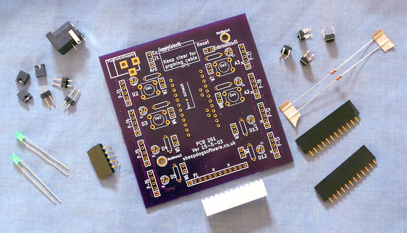
This is NoviceGuard at its most simple: Just the onboard buttons (4), and the LEDs (and their resistors) on the outputs. No daughter boards plugged in. Nothing plugged into PlugForExtSupply.
It doesn't get more basic than this, and yet even this simple set up opens up lots and lots of good programming challenges for the user. the "need" for some "new excitement", in the form of "new (hardware) toys" will probably cause you to move on to more complex power supply scenarios long before your novices have exhausted what can be learned about programming with "just" a NG_PwrDemand_0 circuit.
Besides the four buttons, four LEDs, and resistors, you will also require the pull-ups on inPUR, inPLR to gloss over the difference between analog and digital inputs for the moment.
The JPwrDauSrcSel9 jumper would either be taken care of by the thin trace on the back of the board, or by a "hat" across the middle and lower ("Ard") pins, if you have installed pins, in which case you must have cut the thin trace.
All power would be coming into the circuit via the programming cable.
For some of the later power demand scenarios, I will provide model instructions for novices, but for NG_PwrDemand_0, about all that needs to be said is "Don't mess with things." If the pull up resistors are on pins plugged into the socket, rather than soldered in, maybe say "leave them alone".
Remember that you are dealing with novices. It would be worth saying to them....
"Be sure that the NoviceGuard is always on something non-conductive. It would be Bad if, for instance, it came to rest on a metal pencil case, ruler, table top, etc, etc, and some of the pins could connect through that. Also please be gentle with the device. Make sure it is flat, on something suitable, when you are pressing the buttons, and press them gently."
That's about it, I think for NG_PwrDemand_0... without using the serial monitor.
There are no (electrical) power issues connected with using the serial monitor (http://sheepdogguides.com/arduino/aht1serimoni.htm).
I have "split off" the topic only because I think it makes a logical stage in the journey from your novices from "entirely new" to "expert".
Start them with a NG_PwrDemand_0, no serial monitor user. When they've "got" that, bring them to the benefits of the serial monitor.
They need to add...
Serial.begin(9600);
... to their setup() routine. I would also add, still part of setup(), after the above....
Serial.println("(Program name) Version (version info)");
Incorporation of a version ID (and keeping it up to date!) is a good habit to begin building. (NovGrdCore has a subroutine that sends its version ID: reportVers(); to the serial monitor. It will only work after a Serial.begin() command has been executed.)
Novices will also need to be shown that the serial monitor doesn't open all by itself. As soon as you see "Done Uploading", you click on the button at the right hand side of the development environment software, and the serial monitor opens. You have to re-open it each time you do an upload. Sigh.
-----------
That's about it, I think for NG_PwrDemand_0. Please, please write me if you discover other things novices need to know from their earliest days. (Contact details at the bottom of most of my web pages.)
Only one thing is added with NG_PwrDemand_1: Users can begin using daughter boards.
But only daughter boards which do not make use of the Vcc supplied on one of the pins of the daughter board sockets... or draw very little current from that source.
I think that some kind of labeling scheme is going to be needed for the daughter boards. I haven't fully designed one yet... but it will probably involve symbols rather than colors, for the sake of the color-blind, and so that labels can be generated in monochrome printers.
The scheme will probably indicate the lowest NG_PwrDemand scenario the daughter board can be used under, the power used by the daughter board and which sort of socket it should go in... output, digital input, analog input, either input.
The power flow that an Arduino can tolerate is limited. In perhaps slightly too simple terms, but as a rule of thumb: No single input/output pin should have more than 10mA flowing through it. (Slightly more may be allowed, if you are working at 3v3. Current is only a proxy for power if everything is at a single voltage. The pages which speak of 10 mA being appropriate are strangely quiet on the subject of voltage. They may date from when there were only 5v Arduinos.)
The total current (at 5v) flowing in or out of the Arduino's input and output pins should not exceed 100mA.
These are not the absolute maxima. They are reasonable "everyday" limits.
Under the NG_PwrDemand_1 Scenario, the current flowing from the Vcc sockets of the daughter boards is being supplied from the connected "big" PC's USB port. The Arduino and NoviceGuard will be using some power from that source, and thus the power consumed by the daughter boards must not be too great, or the USB port will be over-taxed.
Don't let this worry you too much. Putting a potentiometer (at least 10k... more, if the noise doesn't become a problem) on a daughter board won't be a big issue. Putting one very bright LED on one might well be asking too much... and several would almost certainly be.
----------------
I wouldn't burden my novices with power demand calculations on the first day they are using daughter boards!
But fairly early on, you are going, I think, to have to put some of the burden of considering how much what they want to connect is going to demand.
A good system of labeling should make it easy enough to stick to safe- for- the- Arduino power demand scenarios.
Under NG_PwrDemand_1 conditions, the LEDS on the NoviceBoard on the input lines should be left disconnected. It is only at NG_PwrDemand_2 and _3 that these can be used to monitor the incoming voltages.
Now you can plug in daughter boards!
Not "just any" daughter boards, though.
There are different sorts. Don't worry too much about putting one in the wrong place. It won't "work", but harm will not arise.
But do, please, worry about putting in too many, or a bad combination of daughter boards. Please pay close attention to your mentor on the subject of "what can it take?"
You wouldn't expect a household light bulb to run well on an AA battery, would you? It is a question of power. Probably not what you think of as power. Something more specific.
Current is not the same thing as electrical power.. but when there's only one voltage involved, we can re-phrase power limit rules as current limit rules.
None of the Arduino input or output pins should be asked to carry more than 10mA. ("Input or output pin", aka "i/o pin"... each push button on the NoviceGuard, each LED is on an i/o pin.)
The total current flowing in all the i/o pins should not go above 100mA.
Your mentor will help you. You may need to disconnect the LED on one or more of the NoviceGuard output lines if a daughter board you want to put on that line allows a "high" current flow. (You simple add the current required by the LED to the current required by the daughter board to know what current the pin would be carrying.
Please don't fall prey to a misunderstanding which results from the way people often talk about something....
Circuits do not "draw" current, not in the sense that a horse "draws" a cart, anyway.
A given circuit will allow, will result in a certain current, if a given voltage is applied to it. We often say it will "draw" that current. But don't, as I said, imagine it is drawing the current the way a horse draws a cart. (It's a bit like the old thing physics teachers go on about... vacuums do not "suck". (Nor does physics in general... electronics is part of physics, after all! But that's another other story.)
Your mentor will provide help on what current the on-board LEDs cause, and what current the different daughter boards available to you would cause.
NG_PwrDemand_2 adds an extra source of power to the circuit. This is supply power to the daughter board circuits. To use it, you need to do things to JPwrDauSrcSel9: cut the trace on the underside between the center and lower pads, add pins, put a shorting "hat" between the center pin and the upper one, "Ex".
qMore needed here? (22 May 15)
When you are given permission to start using the NoviceGuards in the NG_PwrDemand_2 power demand scenario, a whole bunch of new daughter boards join the "safe to use" category.
When you are using a daughter board intended for the NG_PwrDemand_2 power demand scenario, you have to be sure that there are pins at JPwrDauSrcSel9 (upper left, three pin option select jumper), and that a shorting "hat" is in place between the center pin and the upper one, "Ex".
And you need an external power supply connected and switched on.
It the "hat" is in the wrong place, it could damage things. If the power supply isn't there and on, it isn't so bad... but the devices on the daughter boards won't work.
qMore needed here (22 May 15)
The NG_PwrDemand_3 scenario is defined as the one where users start connecting modules to the twelve way connector across the bottom of the NoviceGuard. (Please do not call these modules "daughter boards". Please reserve "daughter boards" for the things that plug into the 5 way connectors.)
I suppose a module for the 12 way connector which didn't need power from an auxiliary supply could be invented... but for the sake of making "the rules" simple, i.e. easy to remember and stick to, I would encourage you to say that any 12 way modules ought to be powered from the auxiliary supply connected via SkFrExtSupply9 and selected with JPwrDauSrcSel9.
qMore needed here? (22 May 15)
.........
THIS BIT STILL TO COME (21 May 15, 09:31), SORRY
These are a few things mentors need to know... but which I hope they can read once, and then "forget"....
There are a number of places where jumper pins can be soldered into the board, to select options (or, no connection across pins, de-select some part of the circuit... just a variation on "select option".)
In some cases, most notably the three pin jumper set JPwrDauSrcSel9, there is a thin trace on the board when it arrives from the manufacturer shorting two of the pads of the jumper set. This this trace creates a default connection between the pads, so that users do not need to solder pins to them before they want the "non-default" state.
If soldering in pins, be sure to cut any such thin trace. It will always be on the bottom side of the board. You must cut the shorting trace in JPwrDauSrcSel9. If you fail to do so elsewhere, "all" that happens is that having no "hat" shorting the pins doesn't achieve what it should.
Arduinos come in 5v or 3v3 versions. You might be doing yourself a favor to choose one for NoviceGuard work at the outset, and stick with that... but NoviceGuards work well with either.
You probably need to have different resistors on the NoviceGuard PCB if using a different Vcc. You may find that some daughter boards, and 12 way connector modules need slightly different components when used with different Vcc's.
There is more on this matter at NGB-VCC.htm
At the upper right, there are two pads marked "SkExtReset9".
Link them, and the Arduino will shut down until you remove the link, at which time, whatever is programmed into it will start executing.
Your novices won't need this for any of their early learning, but the day might come when they have created something they actually want to deploy and use. In which case, a push button can be put on the pads (via a short lead), for making the Arduino restart whenever that is needed. (Of course, if all is well with the program in the Arduino, there's no particular reason why such a situation should arise, is there? And a quick power cycle will do the same thing.)
If the time comes that you wish to use the pads, I would suggest putting a socket on them, not pins.
This page is a sub-page of my Rugguino site, and a sub-page of the information for NoviceGuard (PCB 261). For more information please see the NoviceGuard main page.
I should point out that my "Rugguino" has nothing to do with the much more developed "Ruggeduino" from RuggedCircuits.com. I think we both go back about the same number of years. When I first set up my "Rugguino" domain, I wrote the nice people at Ruggeduino, suggesting that confusion might arise. I think we can live side by side, but be careful not to confuse us.
How to email or write this page's editor, Tom Boyd: http://sheepdogguides.com/ctact.htm
![]() Page has been tested for compliance with INDUSTRY (not MS-only) standards, using the free, publicly accessible validator at validator.w3.org. Mostly passes, just a few "No attribute" issues, arising from Google code.
Page has been tested for compliance with INDUSTRY (not MS-only) standards, using the free, publicly accessible validator at validator.w3.org. Mostly passes, just a few "No attribute" issues, arising from Google code.
....... P a g e . . . E n d s .....