Click this for NoviceGuard main page
Quick word of explanation: This was once the "top" page for NoviceGuard. Following helpful suggestions from people in internet forums, a new top page for NoviceGuard was created. I would guess you came here from there. This page is being wound down. But if the main page didn't answer all your questions, you may find what you want here... but I'd explore the other NovieGuard pages first, if I were you. (There are links to them from the main page, link earlier in this paragraph.)
This page is for people who want more detail. Please read until you get to the "Below here... some of what is above gets repeated" message. What is below there is somewhat untidy, and is for the REALLY interested only! Some material has been removed from this page because it is now part of the "main" pages for the NoviceGuard.
There is a page dedicated to how to obtain NoviceGuards.
At this point, I begin to wonder myself. I'd hoped that there were people out there interested in helping kids and others get started with Arduinos. From the help with spreading the word I've had, I am assuming that no one sees this product as having any merits, or that no one thinks anyone will try to help kids thus.
I've spent time. (many, many hours). I've spent money. (Making boards, getting in components.) I've not asked anyone else to put their money into it. I've not asked anyone else to put their money into it.
I've spent time trying to make a market aware of this project.
And I am beginning to become a little discouraged (14 May 15)... so if you see merit in this, a quick email would be much appreciated.
"Liking", forwarding, mentioning in blogs, etc. would be especially appreciated.
Remember, please, that THIS page is not the "mainstream" NoviceGuard page. It is here only for the really curious.
I hope the following will be useful to everyone... even if it does duplicate some of the material in the specialist pages. (If you are parent/teacher or expert, the specialist pages might tell you enough.)
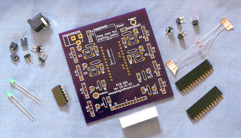
Novice Guard (PCB261) is a small (8cm x 8cm) PCB into which you plug an Arduino Pro Mini. (5v or 3v3).
It has a few pushbuttons, LEDs, resistors, jumpers and sockets on it. (And a plug!).. total cost of easy to assemble (no SMT) kit... probably less than $25.
When given to novices to play with, without further ado, they have four pushbutton inputs they can use to turn four LEDs on or off. ((I will be writing pages full of Example Challenges... if you have some non-obvious ideas to contribute, they would be very welcome!))
The pushbuttons and LEDs are on NoviceGuard... there is no "hooking up" for the novice to contend with... at this stage.
There are a few limitations.... *I* don't think they matter to a novice. What do YOU think?
(The illustration is just to give you an idea of what is involved. In particular, the number of the "bits" needed is not faithfully represented. (But examples of all parts are present.) It is perfectly acceptably to only partially populate the board.)
Video demos at...
YouTube clip showing outputs... 18 seconds' worth. Using NoviceGuard in the most simple possible way. Not showing additional options.
YouTube clip showing an input/ output interaction... 16 seconds' worth. This doesn't feature the options for "advanced" use of NoviceGuard.
If you would be willing to "spread the word", this page can be reached with...
http://tinyurl.com/NoviceGuard
... as well as by the ways you would usually pass the word electronically.
THE FOLLOWING SECTION NEEDS A BIG RE-WRITE, to reflect the availability of the NovGrcCore Arduino library. The library spares the novice much of the following. On the other hand, if you don't want to use a library, you can still do things as follows, which was the original way to use NoviceGuard. (The library merely makes doing the following easier. It doesn't change what is happening.)
Users would have to be told and understand: "Your code must start like this. You must not change the marked lines. You must not add any other pinMode commands. Initially, you will only put new stuff inside the { } s after "loop()"
Yes, I prefer not to hardcode the assignment of pins... i.e. I would have, say, "2" (for digital line 2) in a constant, and use that to refer to the line... but briefly, I would do things "the easy (for beginners) way", if not using NovGrdCore.
Things which can be added via daughter board...
Of course, many, many others are possible... ideas welcomed.
Note: To used outputs which will use more current than an Arduino pin should be asked to service, there is a way to power the daughter boards separately, and the daughter board would use a transistor to switch the device on and off.
As stated more succinctly earlier, I believe that it won't matter! If, say, you plug an LED bearing daughter board into a socket intended for an input, it won't work... but no harm will come to LED or NoviceGuard or Arduino. (?? I hope!! Thoughts of experienced teachers/ electronics people welcome.. but the question is asked better in my audience specific page, created for experts.)
If you haven't already read either (or both!) of my "audience specific" guides, read them first, after, maybe, a glance at the pictures below. (The circuit diagrams are discussed (better) in the guide for experts.)
The guides...
I also offer, more as a proof that serious work and thought has gone into NoviceGuard, than for what it will one day be, if there's interest in the product, an early draft of a User's Guide, intended primarily for tutors using NoviceGuard to get people started, but with sections for the tutors to give (or at least teach to) the users.
For years, I've wanted to produce something to make it harder for novices to harm an Arduino.
The idea was that if this could be accomplished, it would be easier for teachers to bring Arduinos into the classroom.
Well, finally, I have the beginnings of something.
For a pupil's first Arduino work, I suggest LEDs on the NoviceGuard PCB (PCB261), and pushbuttons ALSO on the PCB. It is easy to thus give the pupil access to two inputs, four LED outputs. LOTS can be done with just that. And, before very long, it is easy to give them access to a further two buttons on the PCB.
Thus, for first steps, the pupil can concentrate on the basics of program creation, storing, uploading... and still have some fun. (Ideas for fun projects with just two pushbuttons and four LEDs would be welcome... to ADD TO my own, I hasten to say!)
THEN the pupil can go further, by means of "plug in" daughter boards, which plug in around the sides of NoviceGuard. (Sort of "mini shields", if you like.)
Any input or output for just one line can easily be put on a daughter board. Besides the two digital inputs and four outputs we've already been dealing with, NoviceGuard has "daughter board ports" for two analog inputs.
TESTING IS LIMITED AT THIS POINT
"Version D" boards, the third generation, have been ordered...
The board achieves some flexibility, as we shall see. But the user's "freedom" must be curtailed to achieve the goal of protecting the Arduino from things a novice user might do accidentally.
In particular, for initial use, the lines available are somewhat limited. And a given line is always used for input or output. (The twelve way connector at the bottom of the board gives access to many of the lines that are not easily available to the just-getting-started user.)
Pretty much the rest of this page goes into the details of the functionality offered on the board, and the options you have within each category.
Two "mainstream" pages cover NoviceGuard from a hardware person's point of view. There's an overview, and a second page with more detail of the NoviceGuard hardware. What remains here is scraps to be put in one or the other of them in due course.
In simple use, that connector to the Arduino Pro Mini will also be the source of power for at least the Arduino.
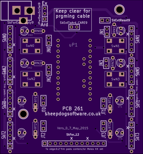
At the bottom left we have provision for two digital outputs from the Arduino. These will be driven by the Arduino pins D4 and D5. The "D4" and "D5" in the silkscreen are to remind you of this. They do not identify the resistors they are near.
(Component naming generally has had a lot of work since this page was written.)
For D4 and for D5, the circuit provisions are identical. You can either send the signals, and a ground, and a power line off board, or you can put an LED (and current limiting resistor) on the PCB. If you've installed the LED and resistor, you can take them out of the circuit by cutting the trace between the poles of the associated two pads which are there for pins, so you can re-enable the LED if you want to put the link back.
When you connect things from off board, the connector scheme discussed elsewhere plays a part in keeping your Arduino safe... as long as the pinMode statements have not be corrupted.
More details are provided in a later section.
At the lower right there is another a pair of lines which have identical (to each other) wiring.
This time we have tapped the Arduino lines D12 and D13. They are set up the same way as the circuits for D4 and D5 are set up.
(Component naming generally has had a lot of work since this page was written.)
There is a little twist you need to keep in mind: Most Arduinos have an LED and resistor onboard connected to D13 even before you "add" the extras my board allows you to have.
The upper left of NoviceGuard gives you positions for two normally open push button switches to pull Arduino lines D2 and D3 low. Or, you can feed those inputs from off the board. An LED (with resistor) is provided to let you monitor the state of the input. Note: You should not attempt to turn that LED on by anything from the Arduino. It is just there to monitor what is coming in.
The design assumes you will avail yourself of the internal pull up resistors provided inside the Arduino. They must be "connected to the lines" by means of pinMode(x,INPUT_PULLUP) in your setup() routine, or by using the provisions of the NovGrdCore Arduino library.
What we have here may come as a surprise to some.
The Arduino lines "A2" and "A3" are normally analog inputs. (Advanced use of pinMode can change that, but that's more than we want to confuse NoviceGuard users with. Teachers using NoviceGuard are encouraged to learn about this, though.)
However, to these analog inputs, NoviceGuard connects the same momentary-switch-to-ground circuit connected to the digital inputs D2 and D2!
Or digital inputs can be fed in from daughter boards plugged into the relevant NoviceGuard socket. Or analog signals can be fed in! All will "work" at one level or another. The software for reading a digital signal on an analog input will be clunky... but it may help beginners with refining their understanding of "digital" and "analog", anyway.
If it really offends you, there are ways to use A2 and A3 as digital inputs (or outputs!), but they entail changing the pinMode statements. I would avoid any use of pinMode (beyond that described elsewhere) for NoviceGuard users. Not messing up the pinMode statements is critical to the success of NoviceGuard in protecting the Arduino. I would urge you to avoid talking about changing them.
A way around asking students to alter the setup()'s pinMode statements (and to remember when they can and when they can't!) is to read A2 and A3 normally, and just treat anything above, say, 128, as a "button not pressed" state, and below 128 as a "button pressed" state.
There is, of course, no need to use any line, and I would postpone introducing the use of A2 and A3 until the pupils have played with D2, D3, D4, D4, D12 and D13 for a while. You can do a lot with "only" two digital inputs and four digital outputs, after all!
At the upper left there is a place (SkForExtSupply9) to connect a barrel socket to accept a source of external power. (You can, of course, just connect wires.) ((q-EXPAND what is AND IS NOT powered by this rail, and why option created.)).
You connect "1" of SkForExtSupply9 to the board's ground line, which is shared by everything on it and the daughter boards.
You connect "2" to 5v or 3v3, depending on the voltage your Arduino is running at. With the socket I used, and the power supplies I plug into it, pin 2 connects to the pin in the center of the socket.
You connect "3" to nothing... but, depending on the design of the socket you use on your NoviceGuard, you may find that pin 3 becomes connected to pin 1... but only when there is no plug in the socket. When no plug is in the socket, it doesn't matter if pin 3... which isn't connected to anything else... is connected to pin 1 and whatever it is connected to. Whew! Easy to use. Hard to describe.
When that is in place, you can use three pins soldered in at "JPwrDauSrcSel9" to select where power for some things comes from. (THIS WILL PROBABLY REMAIN... but the scheme may be widened....) Note that there is a trace (between the middle pin of JPwrDauSrcSel9 and the lower pin, marked "Ard" on the board.) to cut on the back of the board to enable the jumper. (It could be unfortunate if you were to solder in the pins, and connect two of them without first cutting the link on the back of the board.)
If you connect the center pin of JPwrDauSrcSel9 to the pin above ("Ex"), then pin 5 on any of the mother boards, and pin 12 of the twelve way connector, is powered by the source of voltage plugged into the socket we were just discussing, component "PlugForExtSupply".
(On the daughter board sockets, pin 5 is the bottom pin on the left side of the board, the top pin on the right hand edge. Pin 12 of the 12 way connector is the right hand pin. All of this if board lying in front of you with SkForExtSupply9 at "upper" left.)
If the center pin of J1 is connected to the pin below ("Y"), then pin 5 on any of the daughter boards, and pin 12 of the twelve way connector, is powered from the Vcc pin of the Arduino... NOT a good idea, if the daughter boards are going to draw much power.
If you short the two pads marked "SkExtReset9", you will make the Arduino stop working. When the short is removed, it will do a re-boot.
The main use for those pads is to use them to connect to an off-board momentary (normally open) switch. I don't believe that either a pull up or a pull down resistor is necessary. (None is provided on NoviceGuard, anyway!)
Hidden under the pins/ connector for the Arduino's programming cable is a two pin socket named "SkExtToArd_CARE9". EVENTUALLY, when I am more sertain that it is SAFE, I will explain how this can be used to power a pre-programmed Arduino, for use in a target application which doesn't need the serial monitor. Until you hear more from me on this, I suggest you leave these pins unconnected. DO NOT feed a voltage in through them, whatever you do! (Use SkForExtSupply9 and put JPwrDauSel9 to center+"Ard"... if you must "jump ahead" and you will accept responsibility for any damage. (You're accepting this, anyway, but particularly so here!)
Two large holes are just for mounting the board in an enclosure.
There is a page dedicated to how to obtain NoviceGuards.
The name "NoviceGuard" has been chosen carefully not to conflict with other people's products. I have been using it since at least 10 Mar 15. It you have been using the name since before that, and are worried about people being confused, please get in touch.
If you think that this... or what it could become... has any merit, Please help spread the word!
If you would be willing to "spread the word", this page can be reached with...
http://tinyurl.com/NoviceGuard
... as well as by the ways you would usually pass the word electronically. (There are buttons at the top for two ways, Facebook and GooglePlus. If you could tweet about this, or mention it in forums, those would also be greatly appreciated.
This entire project is done for love of the Arduino, and of kids. I've paid all the expenses to date. I get no payment for my time. Please make my time, effort and expense come to something? Sad? Yes, well, maybe... but is the product any good? Will kids benefit from it becoming more polished?
![]() Page has been tested for compliance with INDUSTRY (not MS-only) standards, using the free, publicly accessible validator at validator.w3.org. Mostly passes, just a few "No attribute" issues, arising from Google code.
Page has been tested for compliance with INDUSTRY (not MS-only) standards, using the free, publicly accessible validator at validator.w3.org. Mostly passes, just a few "No attribute" issues, arising from Google code.
....... P a g e . . . E n d s .....