Click this for NoviceGuard main page
If you have not yet seen the "parent" page of this page, it might be a better place to start. It gives an overview of the NoviceGuard PCB's elements. The page you are reading goes into details.
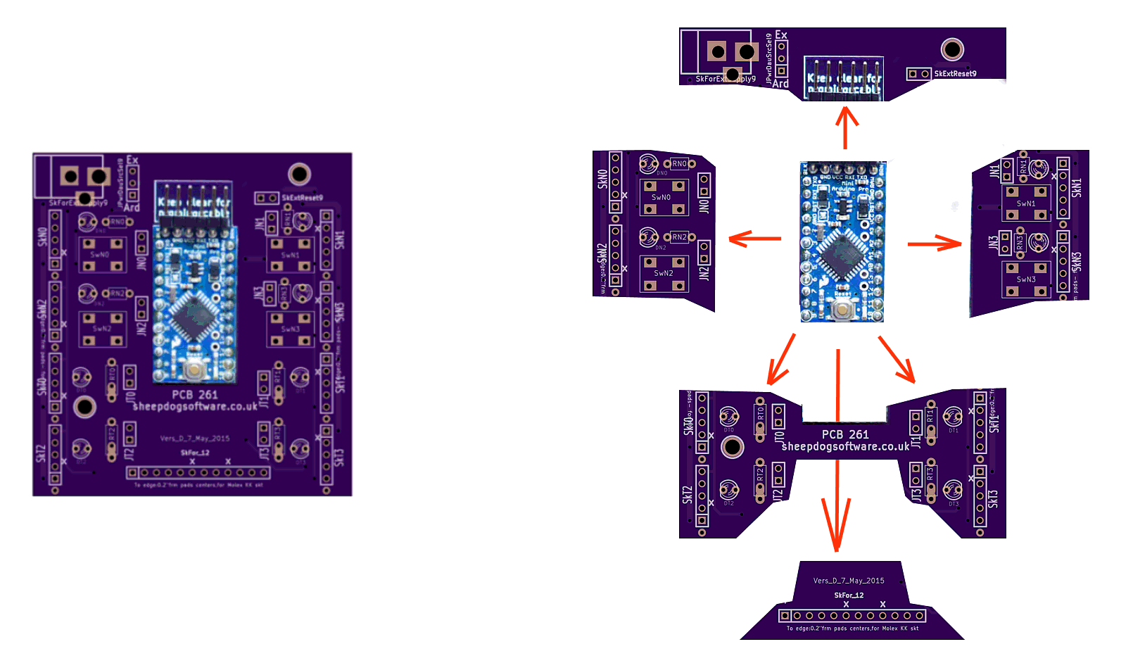
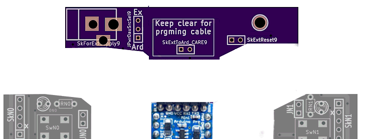
On the left below: an unpopulated NoviceGuard board (purple), with an Arduino Pro Mini (blue).
On the right, the same image, but "exploded", to show you the "parts" of the NoviceBoard. Each part delivers related services from the board.
This page is a sub-page of the information for NoviceGuard (PCB 261). For more information please see the NoviceGuard main page. And, as I said a moment ago, a more detailed look at the NoviceGuard board's parts than the more general overview, which is also available.
PLEASE: Spread the word that NoviceGuard MIGHT be worth looking at, if you want the project to continue. I only ask that people look at the pages, not that they send any money.
There are four output channels immediately and easily available. A very basic NoviceGuard will carry four LEDs... in the positions marked by the yellow "L"s. (NoviceGuard still "works", even if you decline to install some or all of them. That applies to almost any component.)
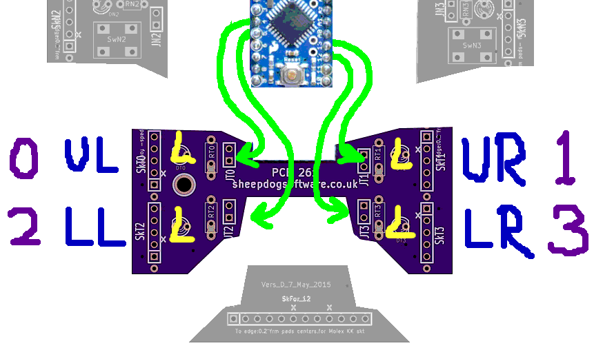
What we see at the above is the part of the NoviceGuard board that provides the user with four outputs. There are pads for four LEDs. The LED names are, from upper left, as you would read a square of four words: DT0, DT1, DT2 and DT3. The names are inspired by, for the first one: "Diode, on ouTput, position zero (0)". This "0,1,2,3" numbering of elements of NoviceGuard... shown with the purple characters near the edges of the image... is used elsewhere. For instance, the NovGrdCore library has output routines....
These routines make one of the OUputs high or low, (LED on or off), depending on the number passed with what's inside the parentheses.
The last part of the names (UL, UR, LL, LR) are for Upper Left, Upper Right, Lower Right and LowerLeft. Those identifiers are on the image in blue, to help convey the logic of their assignments.
There is also a routine, makeOu(bWhich, bState), which will set or clear the output designated with bWhich. It can be 0, 1, 2 or 3, for, respectively, UL, UR, LL or LR. (The pattern is always as you would read four words arranged in a square.)
Users are not restricted to turning an LED on and off. By means of daughter boards, "fancier" hardware can be plugged into the NoviceGuard, to extend what it is your users are driving with the outputs.
The outputs are driven by the following Arduino pins. I hope you will not "trouble" novice users with those names. Either use #defines, or just use the NovGrdCore Arduino library, which takes care of it for you, to set up the following aliases...
Arduino Pin   NovGrdCore Alias  NovGrdCore Index
-----------   ----------------  ----------------
   D4             ouPUL           0
   D13            ouPUR           1
   D5             ouPLL           2
   D12            ouPLR           3
The alias name was created from the following elements... OUtput Pin Upper Left... (and so on for the other three). Please use the same aliases and indices in any demo programs you create for use with NoviceGuard, or with an Arduino with the NoviceGuard inputs and outputs otherwise provided.
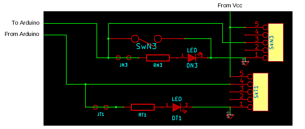
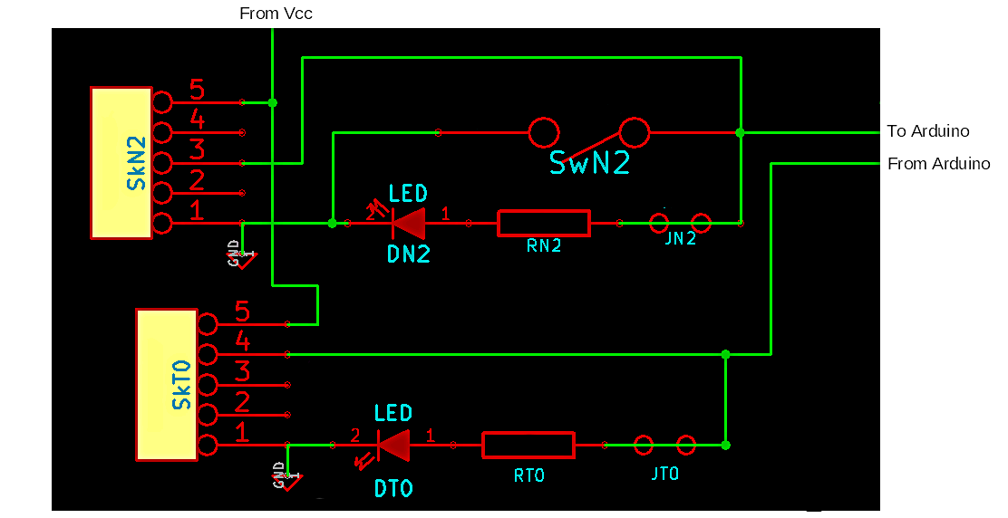
The following is one each of the two types of "feeds" to the daughter boards on the right hand side of the PCB.
Ignore the upper one ("To Arduino" line) for the moment. We'll discuss that under "Inputs"
The lower one, the "From Arduino" line, serves an output, the one from pin 13, as it happens. But NoviceGuard users should not see "13". They would see ouPUR, wouldn't they? (If that doesn't make sense, re-read the material above here, please?)
Nothing in NoviceGuard has been altered because of the LED and resistor provided on that pin on the Arduino Pro Mini, and many other Arduinos.
You can download a PDF of the overall NoviceGuard (PCB261) schematic. The screen shots above were taken from it.
There are four input channels immediately and easily available. A very basic NoviceGuard will carry four push button switches. (Momentary SPST switches.)
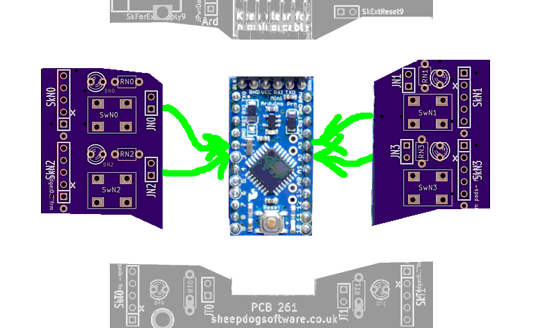
The four switches go at the rectangles marked SwN0, SwN1, SwN2 and SwN3, which I hope you see clearly on the image? (SwN3: SWitch, to provide iNput, in position 3.)
Novice NoviceGuard users can be allowed to think there are four digital inputs. The boardseems to have four similar inputs, if used via the NovGrdCore library. Or if the board is used with the avoid-the-library "tricks" explained elsewhere. Use of the library is optional. Use of the NoviceGuard is optional! Your learners can still use the challenges and help on these NoviceGuard/ NovGrdCore pages!
In fact, the two inputs on the left (Input "0" and Input "2") are indeed simple digital inputs. The two on the right (Input "1" and Input "3") are analog inputs. Intermediate NoviceGuard users can use them as such. But beginners don't need to be confused by the differences. They just use the NovGrdCore function boInHigh(x).
Continuing the convention established earlier, here are the names for pins, and the indices...
Arduino Pin   NovGrdCore Alias  NovGrdCore Index
-----------   ----------------  ----------------
   D2             inPUL           0
   An3            inPUR           1
   D3             inPLL           2
   An2            inPLR           3
The alias name was created from the following elements... INtput Pin Upper Left... (and so on for the other three). Please use the same aliases and indices in any demo programs you create for use with NoviceGuard, or with an Arduino with the NoviceGuard inputs and outputs otherwise provided.
The alias names do not differentiate between the digital and the analog inputs in deference to the needs of people just getting started with NoviceGuard.
The NovGrdCore library has a function....
... which returns a boolean. You put 0, 1, 2 or 3 in as the parameter, and boInHigh will tell you, respectively, if the UpperLeft, UR, LL or LR input is currently high. In a basic NoviceGuard, the input will be high only if the button (switch) is not pressed.
It is really a story for elsewhere, but allow me to digress?....
The following would be at the heart of a simple... and it is simple, isn't it?... "test the buttons and LEDs" program...
if (boInHigh(0)) {makeOu(0,0);} else {makeOu(0,1);};
if (boInHigh(1)) {makeOu(1,0);} else {makeOu(1,1);};
if (boInHigh(2)) {makeOu(2,0);} else {makeOu(2,1);};
if (boInHigh(3)) {makeOu(3,0);} else {makeOu(3,1);};
(End of digression!)
As before, users are not restricted to only the push button switch. By means of daughter boards, "fancier" hardware can be plugged into the NoviceGuard, to extend what inputs are available to your users.
The following shows a bit of the left hand side of the schematic, roughly corresponding to a part of the left hand side of the PCB. It shows you one each of the two types of connections to the LEDs/ switches and daughter boards on the left hand side of the PCB. They serve: an input to an digital input pin, and an output from one of the digital pins.
Ignore the bottom one, the "From Arduino" line. (We covered that above, under outputs.)
The following schematic shows you one each of the two types of connections to the LEDs/ switches and daughter boards on the right hand side of the PCB.
Ignore the bottom one, the "From Arduino" line. (We covered that above, under outputs.)
The upper one ("To Arduino" line" ) provides an input to an analog input pin of the Arduino.
You can download a PDF of the overall NoviceGuard (PCB261) schematic. The screen shots above were taken from it.
There are several options for how the elements of the NoviceGuard, and the Arduino Pro Mini carried by it are powered. There's much on these matters at my pages about the Power Demand Scenarios, e.g. NG_PwrDemand_0. (It isn't as fearsome as it sounds. Can be "just used" by struggling mentors, but helpful, too, I hope, to "mentor mentors".)
The following is from the top of the schematic, roughly corresponding to the top of the board, where there are some "odds and ends". Among them is a dangerous link ("SkExtToArd_CARE9"). (It was not present in the first prototype of the board.) Don't connect those pins unless you really know what you are doing.
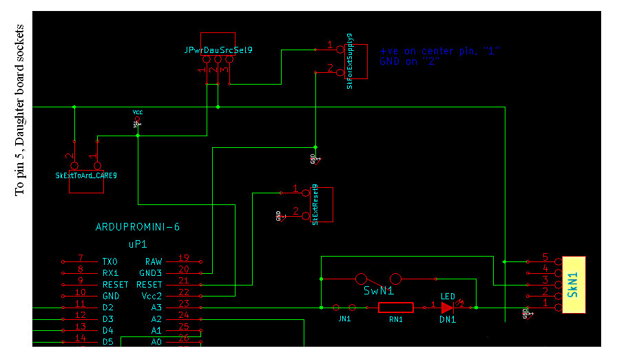
Reset: Before we turn to the power source options, a detail: This part of the board also gives you a socket, "SkExtReset9", for connecting a simple SPST external switch for invoking the Arduino's hardware reset. (It wants to be normally open. No pull up resistors or similar components are required.)
Turning (at last!) to the topic of how what's on the board is powered...
Novice NoviceGuard users should not make changes to the power options; that would be a job for the person introducing the novices to the Arduino.
The matter of choosing how parts of the board are powered takes several pages to discuss. Here's a link to the "reference" page about powering the NoviceGuard. It has links to related pages.
The board comes with a default configuration set up with easily cut traces between the pins of certain feature-select jumpers. (You must cut such traces when you upgrade the jumper position with pins on which a shorting "hat" can be placed when a connection is wanted.)
I promised earlier that NoviceGuard users are not limited to just four lines of input, four of output.
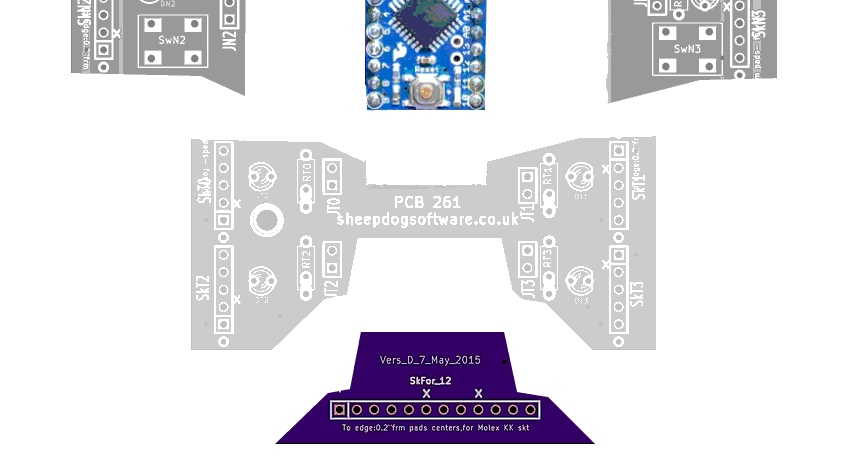
The additional lines are available by plugging daughter boards in to the twelve way socket on the bottom edge of the board.
There is no clever protective circuitry on the NoviceGuard board for these lines, they all just go directly to the 12 way connector. (Ten positions on it carry signals, two are meant to be plugged, to make it difficult to plug in an expansion board incorrectly.)
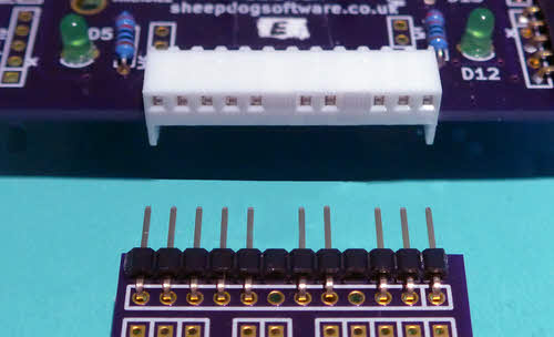
(I used PhotoPlus to "improve" the "no pin here" positions on the socket. Don't imagine that you can buy 12 way strips with positions 6 and 9 so nicely blanked!)
The 12 way connector gives you unprotected access to some more lines, and Vcc, and GND. This is for advanced plug in modules, which I propose calling "Twelve Way Plug Ins". (Please reserve the term "daughter board" for the five way plug in modules.) Some "messing with" pinMode lines will almost certainly be necessary when use of this connector begins. Perhaps an answer would be to have a "code" for different pinMode variations, and mark each daughter board with the code for the pinMode variation it needs?
The 12 way connector gives you access to:
... thus, if you also count what the (five way) daughter board connection sockets let you access, you can access to every digital or analog line of the Arduino, except D0 and D1, which I rarely use, given that they are also used by the programming signals and the system-provided (and often under appreciated!) serial monitor.
Here is what is on the connector, from left to right..
Vcc D9 D8 D7 D6 (n/c) A1 A0 (n/c) D11 D10 Gnd
(Dx refers to a digital pin of the Arduino, and Ax refers to an analog pin.)
Vcc is the 5v or 3v3 (depending on what sort of Arduino you are using) also being supplied to the daughter board sockets. "Gnd" is (of course?) the universal "ground", or zero volts, shared by everything on the board.
The odd order of the pins derives from taking the signals to the board's edge. It is hoped to provide some #defines and sub-routines in free Arduino library NovGrdCore to simplify using things via the twelve way connector.
A minor point: The sharp eyed among you may notice that for the twelve way connector only, Vcc is on "pin 1", which is blessed with a square around it in the silkscreen. Ground is at the other end of the connector. All of the other connectors are set up the other way around. As I say... I suspect that this will pass un-noticed by many users. The blocked holes in the socket will protect you from inserting a module "backwards"... just don't be caught out by the inconsistency when you are designing modules for the twelve way socket. Sorry. (End "minor point"... at least I hope it is minor. Get in touch if you disagree?)
Understand the basic hardware, and you more or less understand NoviceGuard. But other pages give you more detail; they give you the above again but from different points of view.
You can download a PDF of the overall NoviceGuard (PCB261) schematic. The screen shots above were taken from it.
This page is intended only as an overview of the NoviceGuard hardware. Help with programming and electronics is elsewhere.
This page is a sub-page of my Rugguino site, and a sub-page of the information for NoviceGuard (PCB 261). For more information please see the NoviceGuard main page.
![]() Page has been tested for compliance with INDUSTRY (not MS-only) standards, using the free, publicly accessible validator at validator.w3.org. Mostly passes, just a few "No attribute" issues, arising from Google code.
Page has been tested for compliance with INDUSTRY (not MS-only) standards, using the free, publicly accessible validator at validator.w3.org. Mostly passes, just a few "No attribute" issues, arising from Google code.
....... P a g e . . . E n d s .....